Output device assignment with Micro:Bit Playground by 4tronix
Overview of the 4tronix Gizmos
Category
Name of Gizmo
Picture
Description
Links or videos
Digital inputs (blue gizmos)
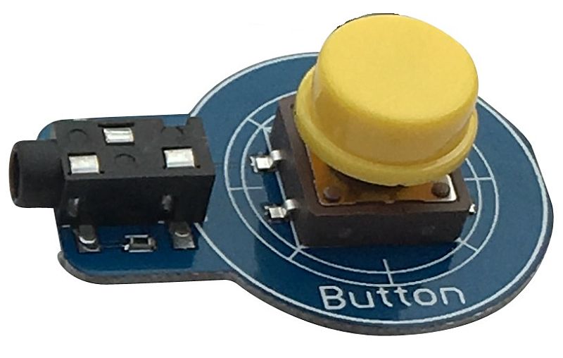
Button
This provides a simple digital input to Playground. It is Active (High) when pressed and inactive (Low) when not pressed. There is a white indicator LED to show whether it is active or not.
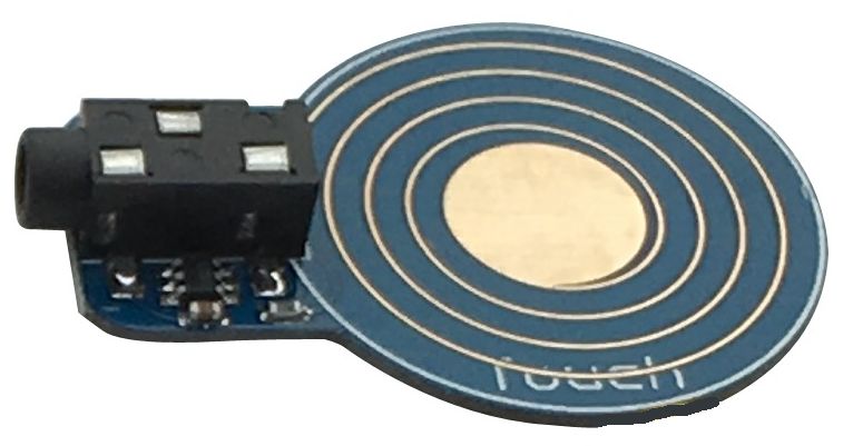
Touch sensor
This provides a digital input to PlayGround. Simply touch the pad on the sensor for it to become active (High) and release for it become inactive (Low). There is a white indicator LED to show whether it is active or not. In fact the sensor will detect your finger without actually touching, so you can do experiments to see how many sheets of paper you can cover it with before it stops working
Analog inputs (yellow gizmos)
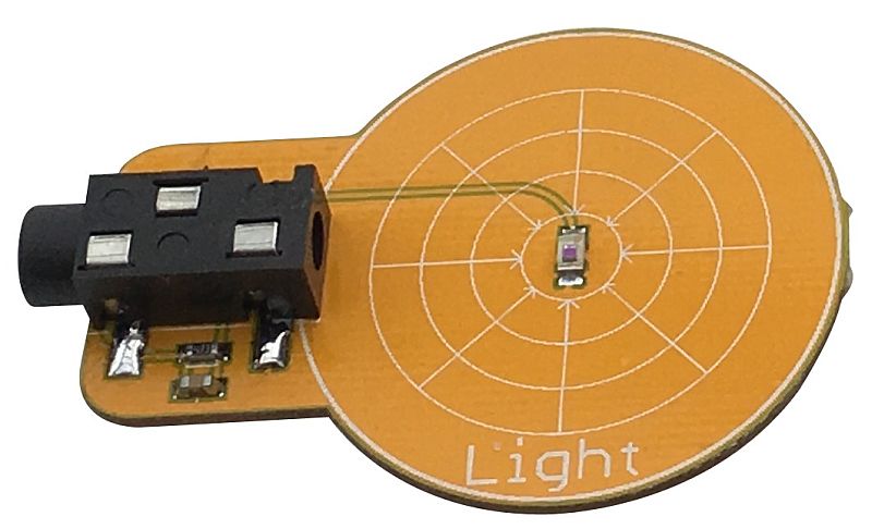
Light sensor
The Light Sensor Gizmo is an anlog input Gizmo that reacts to the brightness of light to the sensor in the centre. It is tuned to be sensitive to daylight. The values vary from 0 (dark) to 256 (bright) on the Crumble, while on the micro:bit it will go from 0 to 1023. The actual top end number will vary due to various losses in the system
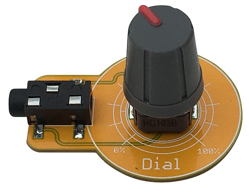
Dial
The Dial Gizmo provides an analog input to your Playground. On the Crumble it will read from 0 to 256, while on the micro:bit it will go from 0 to 1023. The actual top end number will vary due to various losses in the system
Digital outputs (black gizmos)
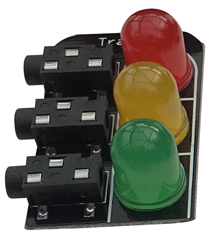
LED (traffic light gizmo)
The Traffic Light Gizmo is a digital output Gizmo for your Playground. Each of the large 10mm LEDs will turn on when the appropriate input is set to High. There are three inputs, one for each of Red, Amber and Yellow
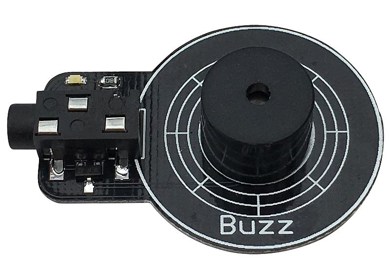
Buzzer
The Buzzer Gizmo is a digital output Gizmo for your Playground. When the input is set to High, the buzzer will sound and a white indicator LED will light
Analog outputs (red gizmos)
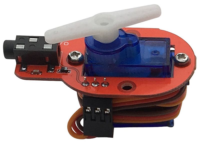
Servo
As the name suggests, this Gizmo allows you to very easily connect a miniature 9g servo to your Playground. Plug it in, then program it for a 180 degree range of movement. With the Crumble, the allowable range is -90 to +90. Do not try and use it outside the allowable range.
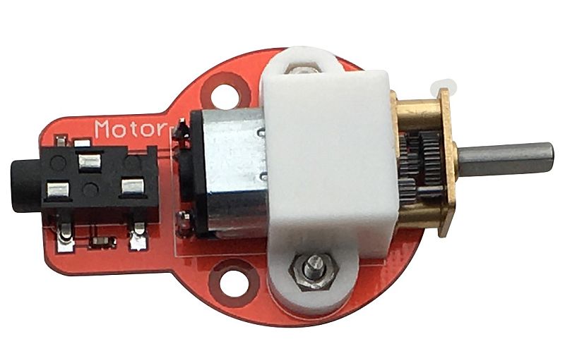
Motor
The Motor Gizmo is driven directly from the Crumble motor driver outputs – it cannot work with the micro:bit. Use the Crumble motor control blocks to set the speed and direction of up to 2 Motor Gizmos. You can build yourself a robot very easily with 2 of these
Smart pixels (White gizmos)
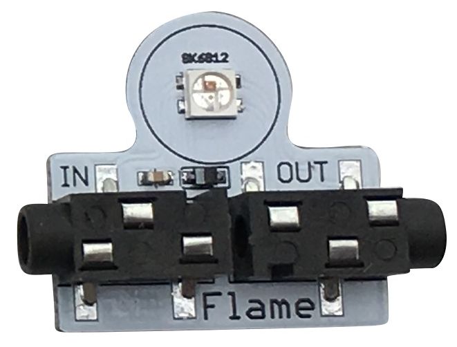
Flame
The Flame Gizmo provides a single, fully controllable, RGB pixel. This allows you to change the colour to any one of 16 million different colours. These are chainable, with both an input and an output connector. On the Crumble, these “smart pixels” are referred to as “Sparkles”, while on the micro:bit they are known as “neopixels”
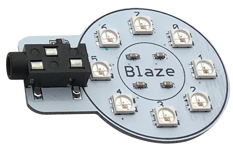
Blaze
The Blaze Gizmo gives you a ring of 8 , independently controllable, RGB pixels. This allows you to change the colour of any or all of them to any one of 16 million different colours. On the Crumble, these “smart pixels” are referred to as “Sparkles”, while on the micro:bit they are known as “neopixels”. These can be added onto the end of a chain of Flame Gizmos if required, or used on their own
Fire stick
Using 4tronix kit to create project where one can control servo with potentiometer
I wanted to start this assignment of using Micro:bit extension called "inventor's kit" in order to test-drive learning materials I have got to my classroom in the Faculty of Education. I did choose exercise where RGB led is controlled by R, G and B buttons. That LED is a special LED that containts three separate LEDs in one package. The lights from these LEDs can mixed together to allow for the creation of many colours
This assigment was fairly straightforward because I didn't want remix it at all. I just did build the circuitry by following tutorial provided by Kitronik and downloaded code by Kitronik. Same goes with the code, which use Micro:bit PWM outputs to take control over the colours of the LED
So my own contribution wasn't something tangible, more or less it was related on learning how kitronik inventor's kit can be used to teach princiliples of the electronics etc.
Configuring circuitry by using breaboard and components
Parts used in this exercixe:
1 x RGB (common cathode) LED
3 x Tact switch
3 x 10kΩ resistor
3 x 470Ω resistor
9 x male-to-female jumper wire
3 x male-to-male jumper wire
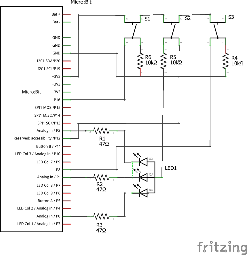
Circuit diagram and breadboard layout
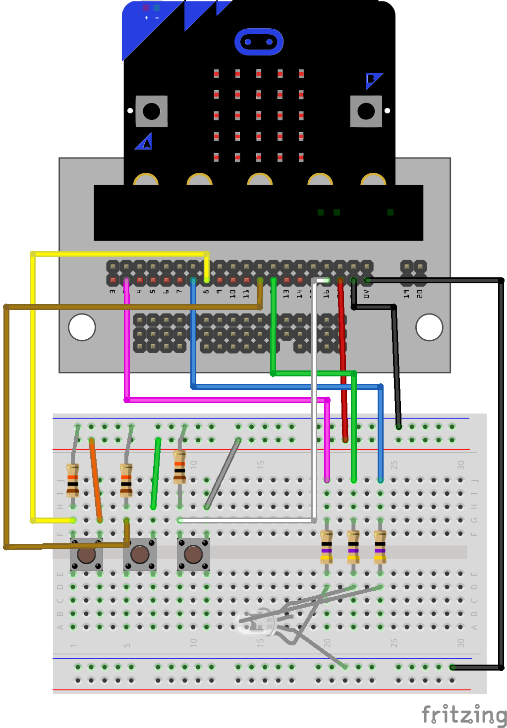
Each switch (see breadboard layout figure below) controls the brigthness of one of the colours (SW1: green; SW2: red; SW3: blue). Pressing a switch will increase the brightness of that switch's colour until cycle will go 0 and colour will turn off.
This circuit uses the three analog PWM (pulse-width-modulation) output pins (pins PO, P1 and P2, see the right figure) from the Micro:bit, on of three colors (separate LEDs) inside RGB led.
When one of the three switches is being pressed, one of the pins (with same color) will output a PWM signal (see pink, green and blue jumper cables in breadboard layout diagram). If switch is pressed longer period, it will raise the analog out value in increments of 10, up to maximum of 1010. If the maximum value is exceeded, then the value is reset back to 0.
The switches has pull-down resistors, which hold S1, S2 and S3 (see circuit diagram picture) low until swithc is pressend at which point current will flow from +3v pin through the switch and made it high
Figure 1. Breadboard layout
Figure 2. Circuit diagram
Micro:bit can be programmed by using Makecode, Micropython or Javascript
MicroPython
The BBC micro:bit is a small computing device for children. One of the languages it understands is the popular Python programming language. The version of Python that runs on the BBC micro:bit is called MicroPython. See more: https://microbit-micropython.readthedocs.io/en/latest/
Makecode and Javascript
Microsoft’s MakeCode editor is the perfect way to start programming and get creating with the BBC micro:bit. The colour-coded blocks are familiar to anyone who’s previously used Scratch, and yet powerful enough to access all the features of this tiny computer. You can also switch to JavaScript to see the text-based code behind the blocks. See more: https://makecode.microbit.org/reference
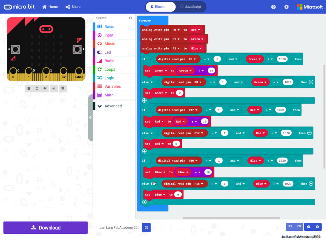
Below is code for this exercise which has been done by using graphical Makecode interface. Makecode is suitable for my lessons in the faculty of education where I teach computer sciences and educational technology to teacher education students
Codebase is running in the forever loop, where three swiches are listened and if one of switches gets value =1 when green/red/blue variable(s) are below 1020, code will add value +10 to variable(s). When it will achieve value 1020, then variable(s) wil be set to value 0
Code is pretty simple even for beginners
Figure 3. Makecode program
Next example is machine generated javascript code, which can be revealed when coding with makecode. When you flip "blocks-javacript" button, graphical coding blocks will be replaced with javascript code. Code is very simple, so it can be used as an example to describe how concepts of computational thinking are present in the code (algorithms, structures etc) but also as an example how to use Microbit I/O pins.
let Red = 0
let Green = 0
let Blue = 0
basic.forever(function () {
    pins.analogWritePin(AnalogPin.P0, Red)
    pins.analogWritePin(AnalogPin.P1, Green)
    pins.analogWritePin(AnalogPin.P2, Blue)
    if (pins.digitalReadPin(DigitalPin.P8) == 1 && Green < 1020) {
        Green = Green + 10
    } else if (pins.digitalReadPin(DigitalPin.P8) == 1 && Green == 1020) {
        Green = 0
    }
    if (pins.digitalReadPin(DigitalPin.P12) == 1 && Red < 1020) {
        Red = Red + 10
    } else if (pins.digitalReadPin(DigitalPin.P12) == 1 && Red == 1020) {
        Red = 0
    }
    if (pins.digitalReadPin(DigitalPin.P16) == 1 && Blue < 1020) {
        Blue = Blue + 10
    } else if (pins.digitalReadPin(DigitalPin.P16) == 1 && Blue == 1020) {
        Blue = 0
    }
})
LIVE Demo of controlling RGB led by using pushbuttons for changing R, G and B colors.
Figure 4. Example of changing color of LED by pushing button. NOTE: gif animation is short and camera doesn't recognize colors perfectly.
Next step: ESP8266 NodeMCU project (how to measure potentiometer and show values in the webpage)
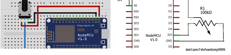
In this exercise, I will show how to check the potentiometer values (resistance) by NodeMCU development board (ESP8266) and then show value by using intergrated webserver to visitors
Required hardware and software
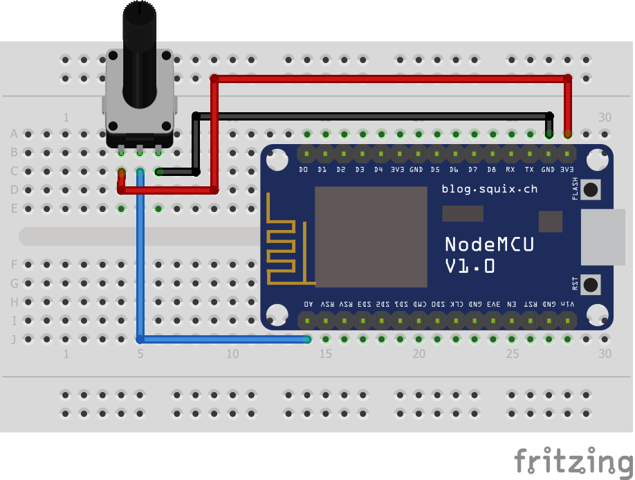
This input exercise is pretty simple what comes to electronics, because only NodeMCU and one potentiometer is required for this task (and necessary cables and breaboard of course)
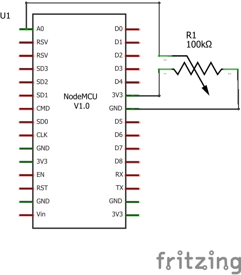
Circuit diagram and breaboard layout
In this exercise we will use only linear (rotary shaft) potentiometer (10Kohm). It will be wired to NODEMCU by using three wires: ground, 3v current and analog input (resistance of the potentiometer, which will be measured by the NODEMCU)
Next step is to create sketch (code) in Arduino IDE and upload it to ESP8266
Now next step is to configure ESP8266 to run as an standalone www-server and measure analog input (potentiometer) value to be shown on simple webpage
Preparing the Arduino IDE
In order to be able to program ESP8266 you need to install Arduino IDE and then install ESP8266 add-on to it. I have explained those pages in the embedded programming week, so please visit here: week 9. Embedded programming.html
In this case you doesn't need to install any other additional libraries, so we can proceed to create actual sketch!
Displaying potentiometer value on ESP8266 web server
Now, I am going to explain how to configure ESP8266 into Station (STA) mode, and create a web server to serve up web pages to any connected client under existing network
First step is to check what are details of your wifi network. Before uploading the sketch, you need to modify the following two variables witrh your network credentials, so that ESP8266 can establish a connection with existing network
const char* ssid = "YourNetworkName";  // Enter SSID here
const char* password = "YourPassword";  //Enter Password here
In the following code sketch you will see different segments of the code commented, which will help you to understand how this simple potentiometer www-server will work in the practise
/* Simple code, which will measure potentiometer value and
 *  show it on internal ESP8266 webserver
 */

// include ESP8266 www-server library, which do turn ESP8266 into www-server
#include <ESP8266WebServer.h>

// Analog input A0 is defined to be potentiometer
#define Potentiometer A0

// let's define variable potvalue where potentiometer value is stored
float potvalue;

// wifi settings (these variables need to be adjusted to fit into wifi network )
const char* ssid = "ubinotko1";
const char* password = "";

// www-server will be set up to answer in port 80 and can be called as server in the code
ESP8266WebServer server(80);


/*
*    Following codes are run once; this is the spot for setup and configuration
*	- In this program this section is used to start www-server and serial-connection (for debugging)
*
*/
void setup() {

// serial connection is openeded
  Serial.begin(115200);
  delay(100);

// this code puts SSID name to serial console
  Serial.println("Connecting to ");
  Serial.println(ssid);

//connect to your local wi-fi network
  WiFi.begin(ssid, password);

/*check wi-fi is connected to wi-fi network.
* If connection is not established "." will be displayed until connection is ok
*/
  while (WiFi.status() != WL_CONNECTED) {
  delay(1000);
  Serial.print(".");
  }

// When wifi connection is established, serial console will show following messsage
Serial.println("");
  Serial.println("WiFi connected..!");
  Serial.print("Got IP: ");  Serial.println(WiFi.localIP());

 // if page request is ok, show handle_onconnect, if not found, then show handle_not_found
  server.on("/", handle_OnConnect);
  server.onNotFound(handle_NotFound);

  // start server and show it also via serial connection
  server.begin();
  Serial.println("HTTP server started");
}

/*  Put your main code here, to run repeatedly:
*	In the context of code this section is used only to listen port 80 (wait potential visitors)
*
*/

void loop() {

server.handleClient();

}

// When page request is done by visitor(s) this section will read potentiometer and send it to www-pages
void handle_OnConnect() {
    potvalue=analogRead(Potentiometer);
	server.send(200, "text/html", SendHTML(potvalue));
}l

// if requested page is not available, then show error 404 message
void handle_NotFound(){
  server.send(404, "text/plain", "Page Not found. I am sorry :(");
}

// This is full html page which will be shown to visitor
String SendHTML(float potvalue){
  String ptr = "<!DOCTYPE html> <html>\n";
  ptr +="<head>\n";
  ptr +="<title>ESP8266 Potentiometer value (resistance) www-server ;-)</title>\n";
  ptr +="<style>html { font-family: Helvetica; display: inline-block; margin: 0px auto; text-align: center;}\n";
  ptr +="body{margin-top: 50px;} h1 {color: #444444;margin: 50px auto 30px;}\n";
  ptr +="p {font-size: 24px;color: #444444;margin-bottom: 10px;}\n";
  ptr +="</style>\n";
  ptr +="</head>\n";
  ptr +="<body>\n";
  ptr +="<div id=\"webpage\">\n";
  ptr +="<h1>ESP8266 Potentiometer Value Station\n";
  ptr +="<p>Resistance: ";
  ptr +=potvalue;
  ptr +="Ohm</p>";
  ptr +="</div>\n";
  ptr +="</body>\n";
  ptr +="</html>\n";
  return ptr;
}
Reflections and possible next directions
In this "input devices" assigment I wanted 1) to test Kitronik Inventor Kit (electronics extension to Microbit) and makecode programming with Micro:Bit and 2) to explore how to connect ESP8266 via wifi and show values in www-server
ESP8266 is important device for me, because I will use newer version if it in the context of my final project. So in my electronics explorations I will use ESP8266 as much as possible.
I was surprised how easy it was to measure analogical input of ESP8266 and turn it into www-page
Next steps with ESP8266
I will continue with ESP8266. Following explorations will be done in the context of the Fab Academy or outside of it:
Using MQTT to exchange data between of ESP8266 and other devices
Adding sensors to ESP8266
Adding servos and motors to ESP8266
etc..
In the context of my Final project I will use successor of ESP8266: ESP32 for following purposes